How to enhance the robotic experience
with Scratch
Javier Arlegui, arleguip@unavarra.es
Dept. of Psychology and Pedagogy, Public Univ. of Navarra, C. Arrosadía, Pamplona, Spain
Michele Moro, michele.moro@dei.unipd.it
Dept. of Information Engineering, Univ. of Padova, Via Gradenigo 6/A, 35131 Padova, Italy
Alfredo Pina, pina@unavarra.es
Dept. of Math. and Computer Eng., Public Univ. of Navarra, C. Arrosadía, Pamplona, Spain
Abstract
The paper shows how deep a robotic
experience can be using the Scratch environment. After some motivating reflections
and remarks, the paper presents a sequence of demonstrative examples exploiting
most of the Scratch commands able to promote such an experience. In the
conclusions the possibility of using external hardware is also mentioned.
Keywords
Educational robotics, Scratch, Constructionism,
IBSE
Introduction
When you read a paper or a report on the
educational use of robotics, most times it is put in connection with the
constructionist approach (Bers et. al., 2002; Goldman et. al., 2004, Chang et.
al., 2010). This is not surprising: the original Papert’s turtle was a drawing
robot, basic educational robots like Bee-bot and Pro-bot (see http://www.tts-group.co.uk)
are programmed with Logo-like primitives, and very often simple robot motion
examples are based on commands very similar to the turtle’s motion commands.
Moreover most researchers agree on considering constructionism the correct and
effective way both to introduce elementary robotics and to exploit all the
educational potential that robotics can convey (Demo et. al., 2012).
In this sense Scratch (http://Scratch.mit.edu/)
is not an exception: this successful legacy of LOGO tradition has various
relations with robotics: it includes several commands to give sprites a stronger
robotic apparatus, it is interfaced with external devices like Picoboard and
LEGO WeDo useful for realizing physical robotic constructions, it has been
extended to control a LEGO Mindstorms NXT or an Arduino system (http://www.arduino.cc/).
Through a sequence of documented examples, this paper presents motivations for
using Scratch to have an initial, deeper robotic experience before starting
with a physical robot. Coming from our previous experience in Educational
Robotics, this is a preliminary result of our research that, without denying
the fundamental value of working with real robots in a real environment, can show
how it is possible to have a rewarding experience in a known and widespread
virtual environment, anticipating most of the competences successively developed
with a real robot. A teacher could promote this approach designing a
constructionist progression from Scratch as an authoring system, from Scratch
as a virtual robotic environment, from Scratch with external devices for
teaching control principles, towards the use of an autonomous real robot to
face the uncertainties of the real world.
In the second section we provide some
general motivations and discuss critical aspects that the literature and our personal
experiences show. The third section is dedicated to the set of examples: as an
auxiliary compact notation for this paper to present Scratch code, we will use
a textual language which is defined and used in the official Scratch wiki and
forums (http://wiki.Scratch.mit.edu/wiki/Block_Plugin/Syntax). Some final
remarks conclude the paper.
Robotics at school: motivations and
criticalities
Papert's great contribution was to build a
educative “medium” specially adapted for children to make learning processes
compliant with the psycho-genetic theories of Piaget (Piaget, 1972). The medium
was a cinematic object: the LOGO turtle and a structured language of commands
and functions to manage its behaviour, the LOGO language. Papert actually
designed (without knowing it) one of the first educational robots (Papert,
1980).
The educational proposals based on Piaget's
theories were initially radical: they were based on his proposition that “every
time we teach a child something, we prevent him from finding it out by himself”.
Here we see the initial foundations of an active-autonomous learning through self-discovery
that will be transformed, with Vygotsky's social contributions (Vygotsky, 1968),
in active-driven learning through exploration/inquiry, i.e. what we identify
today as social constructivist learning. Thus we see that the genesis of
robotics at school, and of the methodological reasons for its introduction, derives
from the conjunction between Piaget and Papert.
Enabling students to have “real” learning experiences
(in the Piaget's sense) has been the main motivation of the development of LOGO
in compulsory education. It is the methodology, rather than the content of
learning, that matters, and the last educational goal was “learning to learn”.
The direct examination of physical objects by the child, according to Piaget, allows
him to build logical schemas of concrete operations and to gain a equilibrium in
the scope of his interaction with the environment.
But the exploration of the turtle exhibits
substantial differences. You don’t touch the LOGO turtle, you cannot directly interact
with it, but only through its programming language. A “physical” exploration in
the behaviour of the turtle is done through the linguistic exploration of its formal
programming language. It is an indirect exploration, mediated by language. Though
being a concrete exploration activity it is applied on a formal context, and in
this case the discovering activity of the child allows him to build their own
logic schemas of formal operations. The benefit of young people working with LOGO
programming environment is to allow extending the same Piagetian methodology of
learning through discovery to the construction of cognitive patterns of formal
operations.
Clearly, in this first stage of “robotic learning”
the greatest interest is in the functional and constructivist learning of the programming
language as a vehicle for a constructivist learning of the formal spaces and their
rules for the representation and communication of the world, for making
students access the formal competences.
Common implementations of LOGO provide a
working scenario (the environment) where we can control “actors”. The language
allows the interaction between actors, but does not realize the interaction
between actors and environment. The environment is a purely decorative stage, a
drawing of pixels, and an actor (turtle) can only detect the colour of the
pixel on which is currently located. This leads to the design of microworlds
usually without a stage, where the requested tasks and procedures are not
dependent on the environment and deal with how to construct certain completely
pre-determined geometric paths If you consider the usual LOGO procedure to draw
a regular polygon, the task of the turtle is not conditioned by the
environment. Consequently LOGO primitives commonly used in this kind of
problems are commands and arithmetic functions for the movement of the turtle and
the control statement "repeat". On the contrary, the conditional
statement "if" is much more rare.
But an hypothetical-deductive thinking can
be more complex, and it reaches a second level of abstraction when formulating
and validating hypotheses about appropriate “behavioral conditions”. They are
hypotheses about the variables expressing interactions with the environment: sensorized
robots interact continuously with the environment.
Scratch offers advantages as an evolution
of LOGO. While promoting, like LOGO, basic hypothetical thinking, its design moves
around a more advanced interactive language and may allow, on the one hand, the
simulation of “physical” environments and, on the other hand, the enrichment of
its “sprites” with simulated sensors, i.e. it permits to work on the second
level of the hypothetical-deductive thinking. This will be exemplified in the
following sections.
Similarly as the LOGO turtle, a Scratch “virtual
robot” has some advantages over physical robots, which are worth considering if
you are more interested in a school constructivist work. These advantages regard
the unavoidable uncertainty of a physical robot when translating into actions a
given task. There are unavoidable differences between the values of the real structural parameters of a robot (influencing the actual
behavior of the robot) and the theoretical parameters of the robot model (which
are taken into account when solving the requested tasks).
For example, common differences are in the actual wheel radius, in the actual width
of the shaft between the driven wheels, etc.). There are also limitations on
the engine power, the measurement accuracy of the sensors, there is uncertainty
in the trajectory due to the inertia and friction, ... This causes a physical
robot to implement a “conceptual” macro-task with imprecision. For example, it
is hard to make the robot move straight and turn on the perimeter of a perfect hexagon,
reaching a final state that is identical to its initial state. This is not due
to an error in the formulation of the task (in the programme coding), but to an
inaccuracy which is usually more significant in less sophisticated robots, such
as in educational robots.
Scratch virtual robots, such as LOGO
turtles, have not this problem because its accuracy is of the order of the
density of pixels on the screen, which at present is high enough to consider it
as an ideally perfect robot, at least in their 2D motions.
The immediate availability of the robot contributes
greatly to maintain the motivation to advance in the constructivist process and
to realize an effective learning. Conversely, the difficulty of having a
personal physical robot (or one robot for a small group of students) sometimes makes
hard, or even cancels it, a true exploratory learning. The requirement for
direct interaction with the robot (even mediated by the programming language)
is also here, in a “formal” constructivist learning, as important as it is in a
“concrete” constructivist learning.
Robotics in Scratch
We present here a sequence of small
demonstrative examples which show how deep the ‘robotic’ experience with Scratch
could be. These examples were developed using the current 1.4 version. In some
cases scripts were defined with the role of parameterized functions: thus a
BYOB (http://byob.berkeley.edu/) implementation would be even more effective.
Simple motion
In (Alimisis et. al., 2009) the first examples
proposed regard a simple straight-line motion in order to have a first
deepening of the basic involved physical entities: space, time, linear and
angular speeds. Scratch provides two ways to finely control motion: the glide basic command and using the timer support.
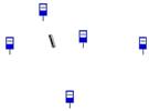
Starting from the simple example of a bus
which has to stop in front of bus stops at fix distance (fig. 1, labels are
independent, not moving sprites), let us set the stopDis variable to
this distance and busSpeed to the requested bus speed, (space is
measured in steps, the unit used by Scratch; time in seconds, thus speed is
measured in steps/s), numStops the number of stops and waitStop the
time the bus must stay at the stop before moving to the next one. The main loop
to implement the travel is the following:
repeat (numStops)
glide ((stopDis)/(busSpeed)) secs to x:
((x position)+(stopDis)) y: (y position)
wait (waitStop) secs
end
|

|
Figure 1. Simple bus motion
Unfortunately, there is no glide version
where motion is specified in a relative form, i.e. using direction and
distance, more reasonable for an autonomous robot which usually cannot refer to
absolute Cartesian coordinates. Thus in our simulation we must calculate them.
When stops are in random positions, you can
use the point towards to re-orient the moving sprite towards the next
fixed stop, whereas the distance command evaluates the distance to be
travelled for the next tract. These two commands can be seen as sensors of the
robot sprite that return respectively the relative direction and distance of an
object. Destinations are identified by sprite names, suitable chosen to
facilitate their enumeration. The absolute coordinates of each target sprite
are now calculated using the x position of sprite and y position of
sprite commands (fig. 2).
repeat
(numStops)
change (i) by (1)
set [stopName v] to (join [Stop] (i))
point towards (stopName)
glide ((distance to (stopName)) / (busSpeed))
secs to x: ([x position v] of (stopName)) y: ([y position v] of (stopName))
point in direction (90 v)
wait (waitStop) secs
end |
|
Figure 2. Random positions
of stops
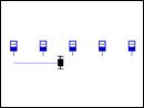
When bus stops are on a straight line but
not at known distance, and we want the robot to recognize stop labels, we
should provide it of a suitable sensor. This can be
simulated using the color <color1> is touching <color2> ? boolean
block. For example, if we add a small red filled rectangle in front of the bus
‘costume’ (shape) and we know that the label pedestals are black, the following
code works (fig. 3, notice the color codes):
repeat (numStops)
repeat until <color [#FF0000] is
touching [#000000] ?>
glide (((busStep)/(busSpeed))
-(0.06)) secs to x: ((x position) + (busStep)) y: (y position)
end
wait (waitStop) secs
move (busStep) steps
end |
 
|
Figure 3. Sensorized bus
The bus moves through a small amount of busSteps steps and the speed is correspondingly tuned, including a 0.06 s of delay.
The final move shifts the bus over the current label pedestal.
Obstacle avoidance
Obstacle avoidance is a very typical
robotic challenge: we present here some examples of increasing complexity to
show the wide spectrum of possibilities.
In the first example we assume to know the
name of the ‘obstacle’ sprite. touching <obstaclesprite> ? returns
true when the current sprite touches the other one in any point of their respective
shape boundaries. With the code of fig. 4, if you put the robot sprite below
the obstacle on its vertical, when the sprite reaches it, the sprite moves
aside to avoid the obstacle.
repeat until <(y position) > (180)>
change y by (3)
repeat until < not <touching
[ObstacleSprite v] ?>>
change x by (10)
end
end
|

|
Figure 4. Simple obstacle
avoidance
In the second example we have several
obstacles in unknown positions but with known colors. In this case it is not
even necessary that obstacles are sprites: they are directly drawn on the
stage. touching color <color> ? reveals the obstacle proximity. We
use also the touching edge ? block to make the sprite to remain within
the stage boundaries. The red ball, i.e. the robot sprite, ‘dances’ bouncing on
the encountered obstacles and on the edges (fig. 5).
forever // main script
move (3) steps
if <touching color [#000000] ?>
turn right (180) degrees
repeat (10)
move (2) steps
end
turn right (pick random (10) to
(260)) degrees
end
if <touching [edge v] ?>
turn right (pick random (70) to
(160)) degrees
move (4) steps
end
end
|

forever // secondary script
if < (distance to [mouse-pointer v])
< (10)>
turn right (180) degrees
move (30) steps
turn right (150) degrees
end
end |
Figure 5. Bouncing ball
The interaction with the user is increased by
the secondary script of the figure: if you move the mouse pointer near the
moving sprite, it jumps a little. These two segments of code can (and must) be
defined as independent, concurrent scripts, both activated with the when
green flag clicked command. This adds a flavour of concurrency, an
important aspect in robot controlling.
Next, we present a more structured
solution, though the avoidance strategy is still elementary. The touch function returns 1 in touch_yes if the sprite touches one of the
obstacles. To check this, we use touching <obstaclename> ? and again numObst obstacles have known, easily enumerable names (fig. 6). For
conciseness we define a glidedistt function that executes a glide for glidedistt_time seconds and for a distance of glidedistt_dist steps in the current sprite direction.
when I receive [touch v]
set [i v] to (1)
set [touch_yes v] to (0)
repeat (numObst)
if < touching (join [Obst] (i)) ?>
set [touch_yes v] to (1)
stop script
end
change [i v] by (1)
end
//-------------------------------------------------
when I receive [glidedistt v]
glide (glidedistt_time) secs to x: ((x
position) + ((glidedistt_dist) * ([sin v] of (direction)))) y: ((y position)
+ ((glidedistt_dist) * ([cos v] of (direction))))
|
 
|
Figure 6. Touch and
glidedistt functions
The avoidance algorithm could be straightforward:
when during the motion in small steps the sprite touches an obstacle (touch_yes is true after calling touch), it tries to go around it and then it goes
forward along the initial direction. In the following example we want that the ‘going
around dance’ of the robot is performed when the minimum distance of the
objects, which are in the angle of ± 15° with respect to the robot’s axis, is lower
than a given threshold. To evaluate such distances we simulate a distance
sensor (ultrasonic sensor) through the the dist function in fig. 7.
when I receive [dist v]
set [i v] to (1)
set [dist_d v] to (3000)
repeat (numObst)
set [dir_x v] to (<[x position v] of
(join [Obst] (i))> - (x position))
set [dir_y v] to (<[y position v] of
(join [Obst] (i))> - (y position))
|
broadcast [dir v] and wait
if < ([abs v] of ((direction) -
(dir_ang))) < (15) >
if < (distance to (join [Obst]
(i))) < (dist_d) >
set [dist_d v] to (distance to
(join [Obst] (i)))
end
end
change [i v] by (1)
end |
Figure 7. The dist function
The minimum distance is returned into the dist_d variable. The dir function (fig. 8) receives in dir_x and dir_y respectively the x and y components of a bi-dimensional vector and returns
in dir_ang its direction, i.e. the angle of its polar representation. In dist it is called to calculate the direction of the conjunction of the sprite
and the obstacle centres, relative to the sprite direction.
when I receive [dir v]
if < (dir_y) > (0) >
// to distinguish quadrants because sin/cos
are not completely invertible
set [dir_ang v] to <[asin v] of
((dir_x)/<[sqrt v] of ( ((dir_x)*(dir_x)) + ((dir_y)*(dir_y)) )> )>
else
set [dir_ang v] to <[acos v] of
((dir_y)/<[sqrt v] of ( ((dir_x)*(dir_x)) + ((dir_y)*(dir_y)) )> )>
if < (dir_x) < (0) >
set [dir_ang v] to ((0) - (dir_ang))
end |
// main script
repeat until << (x position) > (236)
> or <(y position) > (176) >>
set [glidedistt_time v] to (0.4)
broadcast [dist v] and wait
if < (dist_d) < (minDist) >
// go around
end
set [glidedistt_time v] to [0.2]
set [glidedistt_dist v] to [10]
broadcast [glidedistt v] and wait
end
|
Figure 8. The dir function
The unspecified ‘go around’ section can be
easily improved with respect to the previous example, using the dist function to avoid to go to the side of the first obstacle where another
obstacle is very close (possibly declaring a failure if both sides have close
obstacles).
We only mention a further example where we
have provided a scan function which returns in two lists the distances
and the directions, relative to the robot position and direction, of each one
of the numObst obstacle sprites which are in the range of directions -90°¸+90° (i.e. obstacles
that lie before the robot). This function can be thought as the equivalent of a
“range scanner” sensor, providing distances and angles.
Other sensing
When you know the name of the target sprite,
the two commands point towards <sprite> and distance to
<sprite>, simulating the information usually given by a range scanner,
give a sort of aligning sensor. Such tool can be used to realize simple forms
of approaching and following other objects or moving robots.
The PC microphone is interfaced with Scratch so that it acts as a
sound sensor. The level of the perceived sound can condition a script through
the loudness sensor returning a value in the range 0¸100. Another
possibility we suggest for simulating a robot equipped with a sound sensor, or
a phonometer, is to imagine a source, represented by one sprite, emitting a
sound with a given power and the robot that measures a certain acoustic
pressure level which depends on the source power and the distance. For a
spherical propagating sound, acoustics defines a pressure level at distance r,
measured with the logarithmic scale of dB, as follows:
Lp = Lw – 20×log10 r – 11 (dB) Lw = 10×log10 (W/W0)
where Lw is the acoustic (constant)
power level, that depends from the source, W is the source sound power, W0 is the power of the minimum
audible source, conventionally set at 10-12 W(att). In your program you can assume a certain value for Lw and calculate Lp calculate Lp with the formula above.
Line following is one of the basic robot application using a light
sensor: pointing it towards the floor, it makes the robot to distinguish a
light area from a dark area and therefore, suitably modifying the direction of
the robot, you can maintain it along the border of a black shape on a white
plane. We simulate the comparison of the level measured by the light sensor
with a certain threshold with the on-off response of the touching color
<color> ? boolean block. Consider this simple solution (fig. 9).
goto x: (-170) y: (0)
point in direction (0 v)
forever
move (1) steps
if < touching color [#000000] ? >
turn left (2) degrees
say [Lt]
else
turn right (2) degrees
say [Rt]
end
end |
 
a) Around a circle b) Complex
shape |
Figure 9. Line follower
The robot, represented by a very small red
circle, moves clockwise around the black circle near its boundary.
Unfortunately, even not surprisingly, this simple solution suffers of a certain
instability which makes sometimes the robot fluctuating more or less far from
shape boundary. This is more evident on a more complex shape like the on in fig
4b.
Simulation of a motorized robot
Now we attempt to more precisely simulate a
physical robot with one or two motors, two wheels for imparting the motion energy
and assuming that the robot can turn like a robot turtle.
In the first example we have a one-motor
robot running on a straight line. We have realized a motor command,
similar to that realized in NXT-G for the LEGO Mindstorms NXT robot. It
receives 4 parameters: motor_power, regulating the motor angular speed, motor_dir specifying the direction (forward or backward), motor_dur specifying a
generic duration which depends on its type motor_durtype as follows:
when rot, motor_dur is the number (with fraction) of full
rotations; when sec, it is a time measured in seconds; when deg,
it is the number (with fraction) of degrees to be sweeped. The robot
configuration parameters are the maximum angular speed (maxangspeed) and
the wheel radius (radius). The motor implementation first
calculates in ang the requested motion angle and in angspeed the
angular speed, proportional to motor_power so that speed is maxangspeed when motor_power is 100. The motion is performed in a certain number of
steps long astep units each. So the total distance (dist) and the
corresponding time quantum (tstep) are evaluated. To permit to stop the
movement in any moment, a stop flag is used, set by the concurrent stop command. We also add an lmotor command which receives a linear distance
parameter (lmotor_dist) instead of the motor_durtype/motor_dur couple. Setting the motor parameters you can move forward or backward
the robot in a finely controlled way, for example with the distance stops bus
problem (fig. 1). You can also add the equivalent of a color sensor to the
robot, putting a small colored square on the tip of a protuberance that comes
out from the robot body (fig. 10).
when I receive [motor v]
set [stop v] to (0)
set [angspeed v] to
(((maxangspeed)*(motor_power))/(100))
if < (motor_durtype) = [rot] >
set [ang v] to ((motor_dur)*(360))
else
if < (motor_durtype) = [sec] >
set [ang v] to
((angspeed)*(motor_dur))
else
set [ang v] to (motor_dur) //
degrees
end
end
set [dist v] to
((((ang)*(3.1416))*(radius))/(180))
set [astep v] to (2) // linear step
set [tstep v] to
(((ang)*(astep))/((angspeed)*(dist)))
set [time v] to ((tstep)-(0.1)) // final
instant
reset timer
repeat ((dist)/(astep))
 move ((astep)*(motor_dir)) steps move ((astep)*(motor_dir)) steps
wait until < (timer) > (time)>
if < (stop)=(1) >
stop script
end
change [time v] by (tstep)
end
|
when I receive [lmotor v]
set [motor_durtype v] to [deg]
set [motor_dur v] to
(((lmotor_dist)*(180))/((3.1416)*(radius)))
broadcast [motor v] and wait
when I receive [color v]
if <color [#FF9400] is touching [#FFFFFF]
?>
set [color_color v] to (0) // white
else
if <color [#FF9400] is touching
[#000000] ?>
set [color_color v] to (1) // black
else
if <color [#FF9400] is touching
[#FF0000] ?>
 set [color_color v] to (2) // red set [color_color v] to (2) // red
else
. . .
end
|
Figure 10. The motor command
and a color sensor
The color function returns in color_color a color code. The relative complexity of this coder is due to the fact that in
the current version of Scratch we cannot refer directly to color codes.
The last example is the most complex one because it tries to
simulate a steering robot with 2 drive wheels with separate motors. The move command receives parameters similar to motor, plus move_steer representing the steering level, (0 = no steering, 10 = pivoting). With move_steer=0
the robot go straight and this part of the implementation is equal to the motor command. When move_steer>0, we assume that wl>wr (wl and wr angular speed respectively of
the left and right wheel) and that w is set on the basis of move_power,
whereas wr depends on the steering value.
Say d the distance between the two wheels; the radius R drawn by
the internal wheel is given by (for a detailed description of the theory, see Alimisis
et. al., 2009)
R = d×wr / (wl-wr) = d×(wr/wl) / (1-wr/wl)
For simplicity, we assume a reasonable linear relation between the wr/wl ratio and the steering s.
wr/wl = 1 - 1/5×s R
= d×(1 - 1/5×s) / (1-(1 - 1/5×s)) = d×(5 - s) / s
Say al = αwl× r the length of the arc in radians of radius R+d drawn by the
external wheel, and r the wheel radius. In the motion the steering
radius draws an angle Θ and for its measure it holds:
Θ = al / (R+d) = αwl×r
/ (R+d) = αwl×r
/ ((d×(5 - s) /×s) +d) = αwl×r×s / (d×5)
Θ is the angle drawn also by the two
other radius, R for the internal wheel and R+d/2 for the robot
centre. Thus this latter must draw an arc ac of length:
ac = Θ×(R+d/2) = Θ×d×(10-s) /
(2×s) = αwl×r×(10-s) / 10 (αwl×in
radians)
// stop, angspeed and ang as in motor command
set [dir v] to (1)
if < (move_steer) < (0) >
set [dir v] to (-1)
// dir gives the turning side +1=right -1=left
set [move_steer v] to ((0) -
(move_steer))
end
if < (move_steer) = (0) > // this is
equal to motor
reset timer
else
set [theta v] to ((( (ang)*(radius)
)*(move_steer)) / ((wdist)*(5)))
set [astep v] to (( ((([tan v] of
(1))*(wdist))*((10)-(move_steer)))*(move_dir)) / ((move_steer)*(2)))
set [tstep v] to ( ((ang)*(2)) /
((angspeed)*(theta)) )
set [time v] to ((tstep)-(0.1))
reset timer
repeat ((theta)/(2))
move (astep) steps
turn right ((2)*(dir)) degrees
move (astep) steps
wait until < (timer) > (time)
>
if < (stop) = (1) >
stop script
end
change [time v] by (tstep)
end
change [time v] by ((0) - (tstep))
end

b) line follower
|
// line follower application
set [move_dir v] to (1)
set [move_durtype v] to (sec)
set [move_dur v] to (6000)
set [move_power v] to (100)
forever
boadcast [stop v] and wait
if <color [#FF9400] is touching
[#FFFFFF] ?>
set [move_steer v] to (-2)
broadcast [move v]
else
set [move_steer v] to (2)
broadcast [move v]
end
end

a) the path
|
Figure 11. The steering
robot
We execute this motion of the sprite centre on a arc of circle, which
produces a total rotation of Θ of the sprite axis, repeating Θ/δ small angular steps of δ units. We approximates this micro-motion with a
sequence of move-turn-move commands so that, after one small step, the position
and direction of the robot are the expected ones with a real arc of δ units. It results:
b = Rc× tg (δ/2) = (R+d/2) × tg (δ/2)
= d×(10-s)× tg (δ/2) / (2×s)
So the sprite, executing a move(b), turn(δ), move(b), reaches the correct position and orientation after one step.
Experimentally we chose δ=2 as its minimum feasible value. Fig. 11 shows
an application, a line follower with the robot equipped with the equivalent of
a light sensor. The stop command provides a way to resetting a previous move command (broadcast without wait).
Conclusions
As shown in this paper, Scratch includes
several features which can be attributed to usual robotic behaviours. Carefully
exploiting these features makes it possible for a student to have a significant
experience of ‘virtual’ robotics in a ‘virtual’ environment which is a probably
already known and not complex authoring system. Therefore, before working with
a real robot, most important aspects of robotics having an educative value can
be easily transferred.
Interfacing an authoring system like
Scratch with external hardware can further improve the user robotic experience
and make her closer to the positive learning potential that a real,
full-featured robot exhibits. Scratchboard, LEGO WeDo but especially the
low-cost Arduino system are currently interfaced with Scratch (for example see Scratch
for Arduino (S4A), http://seaside.citilab.eu/scratch/arduino). The smooth
learning progression from basic robotics to experiences with external hardware
is more effective when we start with the ‘robotics’ features of Scratch like
the ones we exploited in our experimentation.
References
Alimisis, D., & al. (2009). Teacher
Education on Robotics-Enhanced Constructivist Pedagogical Methods. School of Pedagogical and Technological Education (ASPETE), Athens, Greece, ISBN
978-960-6749-49-0 (http://www.terecop.eu/).
Bers, M.U., Ponte, I., Juelich, C.,
Viera, A., & Shenker, J. (2002). Teachers as Designers: Integrating
Robotics in Early Childhood Education. Information Technology in Childhood
Education Annual, 2002(1), 123-145.
Chang, C., Lee, J., Chao, P., & Wang,
C. (2010). Exploring the possibility of using humanoid robots as instructional
tools for teaching a second language in primary school. Educational
Technology & Society, 13(2), 13-24.
Demo, G. B., Moro, M., Pina, A., &
Arlegui, J. (2012). In and out of the School Activities Implementing IBSE and
Constructionist Learning Methodologies by Means of Robotics. In B. S. Barker,
G. Nugent, n. Grandgennet, & V. I. Adamchuk (Eds.), Robots in K-12
Education: A New Technology for Learning (pp. 66-92). IGI Global.
Goldman, R., Eguchi, A., and Sklar, E.
(2004). Using educational robotics to engage inner-city students with
technology. In Y. Kafai, W. Sandoval, N. Enyedy, A. S. Nixon and F. Herrera (Eds), Proceedings of the 6th international Conference on Learning Sciences (ICLS-2004) (pp. 214-221), Santa Monica, California, June 22-26, 2004.
Papert, S. (1980). Mindstorms: Children, Computers and Powerful Ideas. N.Y.: Basic Books.
Piaget, J. (1972). The Principles of Genetic Epistemology. N.Y.: Basic Books.
Vygotsky, L. S. (1968). Thought and
language. Mass.: M.I.T. Press.
